 |
 |
| View previous topic :: View next topic |
| Author |
Message |
S1gnature
Joined: 28 Apr 2020
Posts: 22


|
| PIC 16f877a and LM35+LCD |
 Posted: Thu May 14, 2020 8:22 am Posted: Thu May 14, 2020 8:22 am |
 |
|
Hi everyone,
I would like to ask about the communication between temperature sensor LM35 and PIC 16f877a.
I build a hand-made project with those components.
The LM35 Vout is connected directly to AN0 pin on PIC 16f877a.
Here is my code.
| Code: | #define LCD_ENABLE_PIN PIN_D1
#define LCD_RS_PIN PIN_D3
#define LCD_RW_PIN PIN_D2
#define LCD_DATA4 PIN_C4
#define LCD_DATA5 PIN_C5
#define LCD_DATA6 PIN_C6
#define LCD_DATA7 PIN_C7
#include <16f877a.h>
#fuses HS, PUT, NOWDT, NOPROTECT, NOBROWNOUT, NOLVP
#device ADC=10
#use delay(clock=8M)
#include <lcd.c>
void ADC_read()
{
setup_ADC(ADC_clock_div_32);
setup_ADC_ports(AN0);
set_ADC_channel(0);
delay_us(100);
}
void main()
{
int16 temp;
set_tris_a(0xff);
lcd_init();
ADC_read();
while(true)
{
temp = read_adc();
temp = 500*temp/1023.00;
lcd_gotoxy(1,1);
lcd_putc(" LM35 SENSOR ");
//printf(lcd_putc,"%lu",read_adc());
lcd_gotoxy(2,2);
printf(lcd_putc," T: %lu",temp);
lcd_putc(223);
lcd_putc("C");
delay_ms(500);
}
} |

If I use int16 type for the "temp" variable and printf(lcd_putc," T: %lu",temp);, the display number on LCD is a 2-digit number like 24 (of course).
But when I use float type for "temp" and printf(lcd_putc," T: %f",temp); it's a float number like "418.00". I would like to ask why do I have this different display numbers?
Secondly I would like to ask if I config the ADC in CCS correctly? As the temperature number displays on the LCD is like a constant (it's flickering, but around a number like 24 in int16 and 418 in float)
Thank you very much for your time. |
|
 |
Ttelmah
Joined: 11 Mar 2010
Posts: 20056
|
|
| Posted: Fri May 15, 2020 1:34 am |
|
|
OK. Lets start with the /1023. Wrong.
But, I hear you say, the ADC gives 1023 for it's full input, so we need to
divide by 1023....
No. The ADC, gives 1023 out, for one count _below_ it's reference voltage.
It actually behaves as if it was an ADC reading 1024 for 5v, but it stops
when it gets to 1023. So the PIC ADC, can never actually 'read' the
voltage corresponding to it's reference voltage.
If you read the family reference manual (DS33023), you will find the
'transfer function' given as 1LSB = Vref/1024. This is what you should
be using for your conversion.
It'll actually give 1023 for a voltage of about 4.995v.
Well done, on selecting your ADC clock. 
You could actually go to div_16 at 8MHz. But what you have is safe and
sensible.
Now the reason for your odd numbers. You don't say what sort of
temperature you actually have on the sensor?. However lets imagine
it was measuring something at 70C. Voltage is then 0.7v. Read_adc, then
returns perhaps 143. Now 143*500 = 71500. Oops. We have a problem.
An int16 (assuming it is declared as 'unsigned'), can hold 65535 max.
Result the multiplication will overflow...
Now in fact each 'count' on the ADC, corresponds with this sensor, to
0.488C ((5/1024) / 0.01). Much easier to do the conversion as:
| Code: |
//with temp as an int16
temp=read_adc()*49;
lcd_gotoxy(1,1);
lcd_putc(" LM35 SENSOR ");
lcd_gotoxy(2,2);
printf(lcd_putc," T: %3.2lwu",temp);
|
With this, the multiplication at 150C, is still only giving 15052. The %lw
format displays this as 150.52 Only half a degree 'out', and with much
less code. The sensor itself is not that accurate, so the tiny maths
error shouldn't matter.
If you want to do something else with the value, just remember it is now
in hundredths of a degree.
It is also worth realising, that with the division by the correct 1024, you
can 'scale' the maths to avoid the overflow:
temp = (125*temp)/256;
Gives exactly the same result, and won't overflow for any normal value
from this sensor. Just multiplying by 1/4 the value you were using, and
dividing by 1/4 the factor. |
|
|
temtronic
Joined: 01 Jul 2010
Posts: 9631
Location: Greensville,Ontario
|
|
| Posted: Fri May 15, 2020 4:31 am |
|
|
A couple of analog comments...
1) Using VDD as the ADC reference is not the best. VDD isn't exactly 5.00000 volts, so all calculations based on it will be off. A typical LM7805 regulator can be off 5% so your 'math' will give the wrong temperature. It can get worse, depending on what the PIC is doing, just before an ADC reading. Say you turn on an LED, that drops VDD, just a bit, say to 4.90 v, so again the reading and math will be off.
2) Add a small cap on the LM35 Vout / ADC input. Temperatures are slow response sensors, so adding a hardware filter (cap, res+cap, etc.) is good design. If the sensor is off the PCB, consider adding a rail to rail op-amp voltage follower at the LM35 This will 'buffer' the reading, allows for long wiring. I did this for a solar pool heater installation. About 100' of twisted pair (CAT5 cable) and had nice stable readings.
3) Add some kind of 'several readings/ take an average' code. if you take 4, 8, 16 readings, the PIC can quickly get the average with a 'shift right'. I use the Olympic average method, as it removes the highest and lowest of 10 readings, then the FAST average of the remaining 8. I do this with the DS18B20 sensors as well. I take a reading every second, so the LCD updates every 10 seconds. Again, temperature is usually a slow process. |
|
|
S1gnature
Joined: 28 Apr 2020
Posts: 22
|
|
| Posted: Fri May 15, 2020 8:30 am |
|
|
thank you very much temtronic 
I actually have no experience on these hobby projects so your comments are really useful. (The last time you taught me about the realterm software, it's time saver for me). I never realize the problem could even be on the ADC math conversion! I only measure the room temperature so the math could be fine here, but I will take note on this! It's amazing.
I am doing a thorough check on this circuit. I don't know why it's keeping giving the ~400*C on the LCD (so hot).
-When I pulled out the connector (that connects Pin A0 - AN0 and LM35 Vout) on Pin A0, it shows 500*C
-When I plugged the connector again, it shows 409-410*C. Even I use a hair dryer to blow some hot air to the sensor, the temperature remains constant.

I have three other LM35 sensors, it gives the same results.  |
|
|
PCM programmer
Joined: 06 Sep 2003
Posts: 21708
|
|
|
S1gnature
Joined: 28 Apr 2020
Posts: 22
|
|
| Posted: Fri May 15, 2020 9:41 am |
|
|
It shows 5.015 in About section. |
|
|
PCM programmer
Joined: 06 Sep 2003
Posts: 21708
|
|
| Posted: Fri May 15, 2020 10:19 am |
|
|
You are giving us calculated results.
Can you post the raw results ?
1. Measure the voltage coming from the LM35 with a voltmeter or an oscilloscope. Post it.
2. Also post the estimated or measured temperature of the air near the LM35.
3. At the same time, display the raw data from the ADC and post it.
Raw data means it's the immediate output of the ADC (10-bits, in hex or decimal). |
|
|
Ttelmah
Joined: 11 Mar 2010
Posts: 20056
|
|
| Posted: Fri May 15, 2020 12:41 pm |
|
|
It sounds suspiciously as if you are actually getting about 800 from the ADC.
This would correspond to about 4v...
Something very wrong... :( |
|
|
temtronic
Joined: 01 Jul 2010
Posts: 9631
Location: Greensville,Ontario
|
|
| Posted: Fri May 15, 2020 1:41 pm |
|
|
| LM35 wired 'upside down' ??? Vcc to gnd, gnd to Vdd ?? |
|
|
S1gnature
Joined: 28 Apr 2020
Posts: 22
|
|
| Posted: Fri May 15, 2020 9:54 pm |
|
|
Thank you for your replies, I have done some checks on the circuit as follows:
The used LM35 is this type
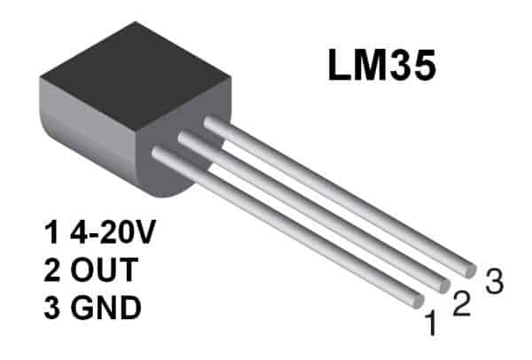
- I checked the voltage on +Vs and GND, it shows approximately 5V (I used an analog voltmeter so I cannot read the exact value, but it is around 5V)
- The temperature of the air near the LM35 is ~30*C.
- The ADC value in decimal ranges from 834-838 (I observed for 2 mins on the LCD). |
|
|
Ttelmah
Joined: 11 Mar 2010
Posts: 20056
|
|
| Posted: Sat May 16, 2020 12:09 am |
|
|
Well, something is radically wrong.
The LM35, should return about 0.3V at this temperature....
You are not going to get the right 'reading', till the LM35 is returning
the right voltage.
5v, implies either the LM35 chip is blown, or the PIC is outputting on the pin
instead of 'reading' on input. The code you post if wired to the right
pin, should be reading an input.
What does the LM35 give if you disconnect the PIC?. What does the PIC show
if you disconnect the LM35?. |
|
|
S1gnature
Joined: 28 Apr 2020
Posts: 22
|
|
| Posted: Mon May 18, 2020 11:46 pm |
|
|
Looks like the problem is on LM35 side. I've done some checks on LM35.
Voltage on LM35 pins:
When everything is connected:
Vcc - GND: +5V
Vout - GND: +4V
ADC value (in decimal on PIC): ~400
When I disconnect pins on LM35:
Vcc - GND: +5V
Vout - GND: +4V
ADC value (in decimal on PIC): ~500 |
|
|
Ttelmah
Joined: 11 Mar 2010
Posts: 20056
|
|
| Posted: Tue May 19, 2020 12:00 am |
|
|
Are you sure there isn't a short to the Vout line on the board?. This
should not be 4v, with the LM35 disconnected. It should be floating, and
tested with a meter, more likely to give a few hundred mV, than 4v.
Are you sure it is connecting to the right pin?.
You have a hardware problem here somewhere. |
|
|
S1gnature
Joined: 28 Apr 2020
Posts: 22
|
| correct result |
| Posted: Sat May 23, 2020 12:23 am |
|
|
Oops sorry, I mean disconnect here is to disconnect the Vout from ADC pins,
it still shows 4V on the Vout pin. When I completely disconnect the LM35, it
shows as you said on the volmeter, just around 0.05 - 0.1V. I tested on
three LM35s and received the same result. I'm not sure if all of them have
been broken. |
|
|
Ttelmah
Joined: 11 Mar 2010
Posts: 20056
|
|
| Posted: Sat May 23, 2020 1:15 am |
|
|
Get a magnifier and check they actually are marked LM35. One explanation
would be that you have been supplied the wrong parts and they are actually
something like a simple transistor.
If they have all come from one place there is the possibility that they
are something like 'forged' parts....
The LM35 is normally quite reliable. |
|
|
|
|
You cannot post new topics in this forum
You cannot reply to topics in this forum
You cannot edit your posts in this forum
You cannot delete your posts in this forum
You cannot vote in polls in this forum
|
Powered by phpBB © 2001, 2005 phpBB Group
|

