 |
 |
| View previous topic :: View next topic |
| Author |
Message |
tonkostz
Joined: 07 May 2011
Posts: 58
Location: Bulgaria


|
| Buzzer sound and interrupts |
 Posted: Tue May 13, 2025 11:17 am Posted: Tue May 13, 2025 11:17 am |
 |
|
I am using the tones.c driver to generate sounds and timer1 to blink a LED but because of the timer interrupts the sound from the buzzer is not clear (choppy).
If i disable the interrupts, sound is perfect and clear.
My actual code is a little bit longer but i shortened it just to demonstrate the problem. Also the LED is not blinking when the buzzer is on. How to handle the timer interrupts and have sounds too?
| Code: |
#include <16f18325.h>
#device adc=10
#fuses RSTOSC_HFINTRC_PLL,NOWDT,NOMCLR,NOBROWNOUT,NOEXTOSC,NOLVP
#use delay(internal=4M)
#include <tones.c>
#define SIZE_OVERC 2 //overcurrent broq na notite
#define LED PIN_C2
#define TONE_PIN PIN_A5
int1 fast_blink=1,LEDx_blink_flag=0,overc=0;
int8 count_mode_blink=5;
const struct //overcurrent beep
{
long tone_overc;
long length_overc;
}overc_beep[] = {B_note[3],200,Bb_note[3],200};//{B_note[3],200,A_note[3],120};
#int_timer1 //Mode and power LEDs blinking
void timer1_isr(void)
{
if(fast_blink==1)
{
count_mode_blink--;
if(count_mode_blink==0 && LEDx_blink_flag==0)
{
count_mode_blink=5;
LEDx_blink_flag=1;
}
if(count_mode_blink<=0 && LEDx_blink_flag==1)
{
count_mode_blink=5;
LEDx_blink_flag=0;
}
}
else count_mode_blink=5;
}
void main(void)
{
setup_oscillator(OSC_HFINTRC_4MHZ | OSC_HFINTRC_ENABLED);
output_low(TONE_PIN);
setup_timer_1(T1_FOSC|T1_DIV_BY_4);
enable_interrupts(INT_TIMER1);
enable_interrupts(GLOBAL);
fast_blink=1;
while(true)
{
for(overc=0; overc<SIZE_OVERC; ++overc)
{
generate_tone(overc_beep[overc].tone_overc, overc_beep[overc].length_overc);
}
if(LEDx_blink_flag==1) output_high(LED);
else output_low(LED);
delay_ms(10);
}
} |
|
|
 |
Ttelmah
Joined: 11 Mar 2010
Posts: 20063
|
|
| Posted: Tue May 13, 2025 11:23 pm |
|
|
Simple truth.
The processor can only do one thing at a time. If you make s sound using
processor operations, and the processor goes off to do something else,
the sound will stop. Hence the breaks.
Solution.
#Use hardware.
Most PIC's offer at least one PWM. Yours does. Use the PWM to generate
the buzzer noise, and this will carry on working while you do other things.
Key lesson, always use hardware to do things if you can. |
|
|
tonkostz
Joined: 07 May 2011
Posts: 58
Location: Bulgaria
|
|
| Posted: Wed May 14, 2025 12:16 am |
|
|
Thanks!
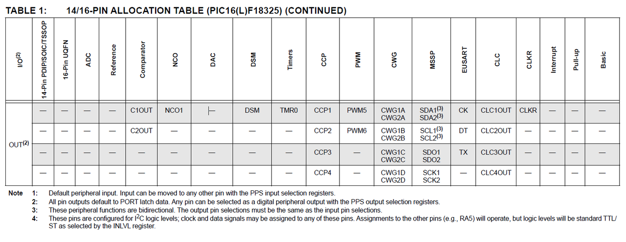
If i understood correctly the datasheet, any pin can be assigned to use the hardware PWM or CCP modules. In the datasheet they say:
"All pin outputs default to PORT latch data. Any pin can be selected as a digital peripheral output with the PPS output selection registers.|
How to do it? For eample how to make PIN A5 to be one of the two PWM hardware outputs? Should call the PPS register directly or the compiler has a direct command for that. I can't find it in the 16f18325.h device file.
Maybe it is this:
"
#bit PWM5OUT=getenv("BIT:PWM5OUT")
#bit PWM6OUT=getenv("BIT:PWM6OUT")
"
 |
|
|
Ttelmah
Joined: 11 Mar 2010
Posts: 20063
|
|
| Posted: Wed May 14, 2025 12:50 am |
|
|
You don't need to access the register.
Look at the sticky at the top of the forum. This is PIN_SELECT. This is what
'PPS' stands for. Programable Pin Select.
If you look in the include file for your processor, you have a section that
gives all the 'FUNCTIONS' that can be routed:
| Code: |
////////////////////////////////////////////////////////////////// PIN_SELECT
// #pin_select function=pin
// Valid Pins:
// PIN_A0,PIN_A1,PIN_A2,PIN_A3,PIN_A4,PIN_A5,PIN_C0,PIN_C1,PIN_C2,PIN_C3,
// PIN_C4,PIN_C5
// Input Functions:
// INT0,T0CK,T1CK,T1G,CCP1,CCP2,CCP3,CCP4,CWG1IN,CWG2IN,MDCIN1,MDCIN2,MDMIN,
// SCK2IN,SCL2IN,SDI2,SDA2IN,SS2IN,SCK1IN,SCL1IN,SDI1,SDA1IN,SS1IN,U1RX,
// U1CKIN,CLCIN0,CLCIN1,CLCIN2,CLCIN3,T3CK,T3G,T5CK,T5G,T0CKI,T1CKI,CCP1IN,
// CCP2IN,CCP3IN,CCP4IN,T3CKI,T5CKI,RX1
// Output Functions:
// NULL,PWM5OUT,PWM6OUT,CLC1OUT,CLC2OUT,CLC3OUT,CLC4OUT,CWG1OUTA,CWG1OUTB,
// CWG1OUTC,CWG1OUTD,CCP1OUT,CCP2OUT,CCP3OUT,CCP4OUT,CWG2OUTA,CWG2OUTB,
// CWG2OUTC,CWG3OUTD,U1TX,U1DT,C1OUT,C2OUT,SCK1OUT,SCL1OUT,SDO1,SDA1OUT,
// SCK2OUT,SCL2OUT,SDO2,SDA2OUT,T0OUT,NCO1OUT,CLKROUT,DSMOUT,PWM5,PWM6,TX1,
// DT1,SCK1,SCL1,SDA1,SCK2,SCL2,SDA2,NCO1
//
|
Understand you have more than two PWM's. You have four CCP peripherals
that can each be programmed as a PWM, and then two dedicated PWM
peripherals. So six PWM outputs available.
You'd need to post the 'generate_tone' code for us to suggest how it
is best done. |
|
|
|
|
You cannot post new topics in this forum
You cannot reply to topics in this forum
You cannot edit your posts in this forum
You cannot delete your posts in this forum
You cannot vote in polls in this forum
|
Powered by phpBB © 2001, 2005 phpBB Group
|

